Introduction
A mid-sized medical device OEM prepares to launch a new diagnostic equipment housing. Confident in their CAD design, they skip prototyping and proceed directly to full-scale injection molding with hardened steel tooling—an investment of $50,000 and eight weeks of lead time. When the first production parts arrive, a critical design flaw becomes immediately apparent: the internal mounting bosses interfere with the circuit board assembly, making the unit impossible to assemble without costly rework. The result? An additional $8,000 in mold modifications, four weeks of production delays, and thousands of dollars in wasted materials. It's a preventable failure that repeats itself across industries every day.
Between 60% and 80% of product quality issues originate from design faults, yet most of these failures could be identified and corrected during prototyping for a fraction of the cost.
Plastic prototype manufacturing involves much more than picking a method. Material selection, design intent, tooling costs, and lead time all interact to determine whether your prototype delivers genuine value or simply delays the discovery of problems. This guide covers the main prototyping methods, key considerations, and best practices to help you reduce risk and reach production faster.
TLDR:
- Prototyping reduces expensive production tooling mistakes—skipping this phase leads to costly rework and delays
- Match your method to your purpose: 3D printing for concept models, CNC for functional testing, thermoforming for large enclosures
- Use production-representative materials in prototypes to get accurate performance test results
- Low-cost prototype tooling (wood/polyurethane) accelerates iteration without committing to production-grade tooling costs
What Is Plastic Prototype Manufacturing?
Plastic prototype manufacturing is the process of producing a physical sample of a plastic component before committing to full-scale production. Prototypes serve multiple strategic purposes — evaluating design accuracy, testing functional performance, gathering stakeholder feedback, and catching failure points early when corrections are still affordable.
In OEM manufacturing, they bridge the gap between digital design files and production-ready parts, providing physical validation that CAD models alone cannot deliver.
Types of Plastic Prototypes
Understanding the three main prototype categories helps you select the appropriate manufacturing method and avoid over-investing in unnecessary precision or under-investing in critical validation:
- Visual/concept models check size, shape, and aesthetics without functional requirements. Useful for stakeholder reviews and ergonomic assessment — no production-grade materials or tight tolerances needed.
- Functional prototypes test fit, form, and real-world performance using representative materials. Must behave like the final part, supporting load testing, drop testing, chemical resistance, or thermal validation. Material selection becomes critical here.
- Pre-production prototypes are near-final parts used for regulatory testing, first article inspection (FAI), or production validation. In regulated industries like aerospace and medical, these go through formal EVT/DVT/PVT cycles and must match exact production specifications.
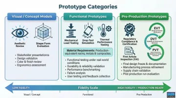
The type of prototype needed directly determines the appropriate manufacturing method. A concept model doesn't justify the cost of a steel injection mold, while a pre-production prototype for a medical device may require the exact production material and process to satisfy regulatory requirements.
Plastic Prototyping Methods: Which Is Right for Your Project?
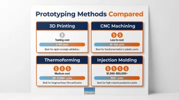
No single prototyping method is universally best. The right choice depends on the prototype type, part geometry, material requirements, and volume. The four main plastic prototyping methods—3D printing, CNC machining, injection molding, and thermoforming—each offer distinct advantages and limitations.
3D Printing
3D printing (FDM, SLA, SLS) is the fastest and lowest-cost option for early-stage concept models. Key strengths include:
- Zero tooling requirements, so you can start immediately
- Quick iterations, often 1-3 days from file to part
- Support for complex geometries that would be difficult or impossible to mold
That said, 3D printing has real limitations for functional testing.
FDM-printed ABS parts achieve only 65% to 72% of the tensile strength of injection-molded equivalents due to layer-line anisotropy. This means a prototype that performs well in 3D-printed form may fail catastrophically when produced via injection molding or thermoforming. The visible layer lines and porous internal structure also limit surface finish quality and dimensional accuracy compared to production processes.
Use 3D printing for concept validation and visual models, but avoid relying on it for functional testing where end-use material properties matter.
CNC Machining
CNC machining is a subtractive process that carves prototypes from solid plastic stock, offering a key advantage: it uses the same engineering-grade materials as production parts—ABS, polycarbonate, PEEK, nylon, and others. Because prototypes are machined from solid stock, they exhibit isotropic mechanical properties identical to production parts—making CNC the preferred choice for functional testing and tight-tolerance validation.
Standard tolerances for plastics run ±0.005" (0.13mm), with precision work reaching ±0.002" (0.051mm). Lead times typically range from 1 to 3 days for expedited orders.
Limitations include difficulty with complex internal geometries (since the tool must physically reach all surfaces) and higher per-part cost for low volumes compared to 3D printing.
Injection Molding
Injection molding is typically reserved for prototype runs of 100 or more parts where representative material properties and surface finish are critical. It's most common during pre-production and regulatory validation phases, where prototypes must exactly match production specifications.
Aluminum prototype molds reduce both cost and lead time compared to hardened steel. Aluminum tooling runs roughly one-quarter to one-half the price of steel, with lead times of 15-25 days versus months for hardened steel production molds. A single aluminum mold can reliably produce 10,000 to 25,000 parts—enough for bridge tooling and extended validation runs.
The upfront tooling investment still makes injection molding impractical for initial design iterations—save it for later-stage validation.
Thermoforming and Vacuum Forming
Thermoforming and vacuum forming heat plastic sheets and form them over a mold, making these methods well-suited for large, low-complexity parts like enclosures, housings, and covers. The key advantage is cost-effective prototype tooling: wood or polyurethane molds replace steel, dramatically reducing upfront costs while still producing functional, production-representative parts.
At Hill Plastics, prototype thermoforming tooling uses CNC-milled wood or polyurethane that can be produced in just a few weeks depending on design complexity. This approach allows engineers to evaluate design function and make necessary changes easily before committing to aluminum production tooling. Once prototypes are approved, the wooden master pattern is used in the aluminum casting process to create the production mold.
Thermoforming is especially practical for industries like aerospace, telecom, medical, and industrial OEMs that need large-format or custom enclosure prototypes quickly without the lead time and expense of injection mold tooling.
Key Considerations When Selecting a Prototyping Method
Before committing to any method, five factors must be evaluated together. Getting any one of them wrong can invalidate your prototype results or inflate costs unnecessarily.
Intended Application and Prototype Purpose
The use case determines everything. A prototype for a trade show or investor pitch has very different requirements than one destined for regulatory submission or drop testing. Define what "success" looks like for the specific prototype phase before selecting a method.
For example, a concept model may only need to demonstrate form factor and aesthetic appeal, making 3D printing entirely appropriate. A functional prototype for thermal performance testing, however, must use the production material to generate valid data.
Part Complexity and Tolerances
Part geometry—including wall thickness, draft angles, undercuts, and internal features—determines which methods are feasible. CNC machining handles tight tolerances well but struggles with complex internal cavities. Thermoforming excels with large, relatively shallow geometries. 3D printing handles complexity best, though tolerance outcomes vary by technology.
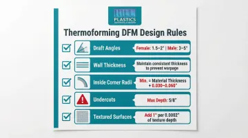
Early DFM (Design for Manufacturability) review catches geometry issues before prototyping begins, saving time and cost during iteration. For thermoforming specifically, key DFM requirements include:
- Draft angles: Female molds require 1.5° to 2° minimum; male molds require 3° to 5° minimum to allow parts to release cleanly
- Inside corner radii: Tight radii down to 0.015" are achievable, but radii should generally equal material thickness plus 0.030" to 0.060"
- Draw ratios: Maximum recommended draw ratio (depth ÷ width or length) is 3:1 to prevent severe material thinning
Material Requirements
If the prototype must perform exactly like the production part—for chemical resistance testing, load-bearing validation, or regulatory compliance—the production material must be used.
The process matters as much as the resin. 3D-printed PEEK behaves very differently than injection-molded PEEK due to poor interlayer bonding and voids. CNC-machined polycarbonate, by contrast, exhibits identical properties to molded polycarbonate because both start from the same base resin.
Common prototyping materials by method include:
- 3D printing: PLA, ABS, nylon (PA12), PEEK (with limitations)
- CNC machining: ABS, polycarbonate (PC), PEEK, nylon, HDPE, acrylic (PMMA)
- Thermoforming: ABS, HDPE, PETG, high-temperature ABS, UV-resistant ASA/ABS, KYDEX
For early-stage prototypes where performance testing isn't critical, a less expensive stand-in material may suffice. But for functional and pre-production prototypes, insist on the actual production material.
Production Volume and Budget
Each method has a different cost structure relative to quantity:
- 3D printing: Near-zero fixed costs but high per-unit cost—ideal for 1-50 units
- CNC machining: Low-to-medium fixed costs, moderate per-unit cost—ideal for 10-100 units where material properties matter
- Thermoforming: Low prototype tooling cost (wood/polyurethane) that scales efficiently to production with aluminum tooling—ideal for 50-5,000+ units, especially large parts
- Injection molding: High tooling cost ($1,500+ for aluminum, $50,000+ for steel) that amortizes over volume—ideal for 500+ units or when exact production process validation is required
Use this formula to compare methods on a true cost basis: Tooling (NRE) + (Unit Cost × Quantity) + Secondary Operations. The break-even point between processes shifts considerably based on volume, and running this calculation early prevents costly method switches mid-project.
Lead Time Requirements
Urgency directly affects method selection:
- 3D printing and CNC machining: Often deliver parts within 24-72 hours
- Thermoforming prototype tooling: Wooden or polyurethane molds can be produced quickly compared to machined steel molds—typically a few weeks depending on complexity
- Injection molding tooling: Adds weeks (aluminum) to months (steel) to the timeline
Faster iterations early in development reduce total project timeline and cost. Choosing a method that enables rapid design changes—such as thermoforming with wood tooling that's easily modified—accelerates the validation cycle.
Design for Manufacturability (DFM) Best Practices
DFM (Design for Manufacturability) means designing parts from the start so they can be manufactured efficiently using the intended production method—not just the prototyping method. A part that 3D prints perfectly may still fail when injection molded or thermoformed if key design rules aren't followed.
Start with a Production-Ready CAD Model
Prototyping should begin with a CAD file that reflects final design intent. This includes:
- Tolerances for critical features clearly defined
- Draft angles appropriate to the production method
- Wall thickness within the recommended range for the material and process
- GD&T (Geometric Dimensioning and Tolerancing) annotations where precision matters
Both direct 3D model annotations and 2D drawings with key specs are valid approaches — the right choice depends on your manufacturer's workflow. Hill Plastics uses SolidWorks integrated with CNC machining, translating digital designs directly into physical tooling without manual re-entry errors.
Follow Process-Specific Design Rules
Each manufacturing process has specific design constraints. For thermoforming and vacuum forming, following these rules during the prototype phase prevents expensive tooling changes when scaling to production:
- Consistent wall thickness: Variation in material thickness causes uneven heating and cooling, leading to warpage and dimensional inconsistency
- Adequate draft angles: As noted earlier, female molds require 1.5-2° minimum, male molds require 3-5° minimum
- Minimum radii on inside corners: Sharp corners concentrate stress and cause material thinning
- Avoid undercuts: Undercuts generally should not exceed 5/8" in depth; thicker materials require expensive movable core-pulls in the tooling
- Textured surfaces: Draft angles must increase by at least 1° for every 0.0002" of texture depth
Ignoring these rules during prototyping creates a false sense of validation: your prototype may look and function correctly, but scaling to production will reveal costly design incompatibilities.
Validate Early and Iterate
The goal of prototyping is to identify failure points before they become production problems. Plan for multiple prototype iterations — especially at the functional stage — rather than trying to perfect the design before the first build. Each iteration brings the design closer to production-ready.
Key milestones to validate at each iteration:
- Dimensional accuracy against design tolerances
- Material behavior under functional stress or temperature
- Fit and assembly with mating components
Working with a manufacturer that offers engineering support during the prototype phase reduces costly redesigns. Hill Plastics' sales and engineering team (Brad Hill and Cody Hill) provides design review and DFM feedback, helping customers identify potential issues before tooling is created.
Prototyping Tooling: Controlling Costs Without Sacrificing Quality
Prototype tooling and production tooling serve different goals — and confusing the two leads to overspending. Prototype molds are designed for low cycle counts and fast fabrication, not the long-term durability required for high-volume runs.
Tooling material choice drives most of the cost and lead time difference:
- Wood or polyurethane — lowest cost; well-suited for thermoforming prototypes and early functional tests
- Aluminum — mid-cost; used when moderate tolerance requirements need a more dimensionally stable tool
- Hardened steel — production-grade; highest cost and longest lead time, reserved for final production molds
For thermoformed enclosures and housings, wood or polyurethane tooling is entirely sufficient for prototype validation — and significantly faster than any metal alternative. Hill Plastics CNC-mills wood or polyurethane prototype molds, with master patterns typically completed within a few weeks depending on design complexity.
That speed has a practical benefit beyond timeline. If design changes are needed after initial parts are reviewed, modifications to a wooden pattern are straightforward and inexpensive — far easier to address before committing to production-grade tooling.
When does it make sense to invest in more durable prototype tooling? Consider upgrading when:
- Tight tolerances are critical and cannot be achieved with softer tooling materials
- The prototype material is abrasive (e.g., glass-filled resins that wear down aluminum rapidly)
- The prototype run volume approaches 500+ parts, justifying the amortization of higher tooling costs
Otherwise, prioritize fast, affordable tooling to support rapid iteration and reduce time to market.
From Prototype to Production: What to Expect
The transition from prototype to production follows four key milestones:
- Concept validation — confirm the basic design intent and geometry
- Functional testing — verify performance under real-world conditions
- Pre-production validation — EVT/DVT/PVT stages for regulated industries
- Production ramp — scale volume while locking in process parameters
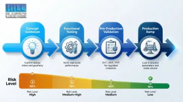
Each stage may use a different prototyping method. The goal is to progressively reduce risk while confirming the design is fully production-ready.
Choosing a prototyping method aligned with the intended production process is critical. Prototyping via thermoforming when the production method is thermoforming means fewer surprises during scale-up — material behavior, surface finish, tolerances, and tooling geometry all translate directly.
The risk of misalignment is real. A team that prototypes via 3D printing but plans to thermoform at production scale may discover incompatibilities late: draft angle insufficiencies or wall thickness variations that simply weren't visible in the printed part.
Those late-stage discoveries are expensive. A manufacturing partner who supports both prototype and production phases avoids costly delays during scale-up. Look for partners who offer design support, engineering review, and produce prototype and production tooling in-house — ensuring continuity from early prototype through high-volume run.
At Hill Plastics, customers start with low-cost wood or polyurethane prototype tooling, evaluate design function, make necessary changes, and then transition seamlessly to aluminum production tooling — with prototyping and production handled by the same team. This eliminates design translation errors that arise when switching manufacturers mid-development and keeps the timeline moving.
Frequently Asked Questions
What is plastic prototyping?
Plastic prototyping is the process of creating a physical sample version of a plastic part or product to test design, function, and manufacturability before committing to full-scale production runs. It reduces risk and validates design decisions early when changes are still affordable.
What is the cheapest method for plastic prototype manufacturing?
3D printing typically has the lowest upfront cost for single or very few parts, while thermoforming with wood or polyurethane tooling offers a cost-effective option for larger or more functional prototypes that need to represent production parts more accurately.
How long does it take to make a plastic prototype?
Lead time varies by method—3D printing and CNC machining can deliver parts in as little as 1-3 days, while thermoforming with prototype tooling typically takes a few weeks for tooling fabrication. Injection molding can take 2-6 weeks due to mold fabrication, even with aluminum tooling.
What materials are commonly used in plastic prototype manufacturing?
Common prototype plastics include ABS, polycarbonate (PC), nylon, HDPE, acrylic (PMMA), and PEEK depending on the method and functional requirements. For production-representative testing, use the actual production material in your prototype to ensure accurate performance data.
When is thermoforming the best choice for plastic prototyping?
Thermoforming works best for larger parts with shallow geometries like enclosures, panels, and housings, particularly when low-cost wood or polyurethane prototype tooling is sufficient and the final part will also be thermoformed in production. It's a strong fit for aerospace, telecom, medical, and industrial OEM applications.
How should I prepare my design before starting plastic prototype manufacturing?
Start with a production-ready CAD file that includes defined tolerances, draft angles, and wall thickness suited to your intended production method. A manufacturer who provides DFM review before prototyping begins will catch design issues early and reduce costly iterations.